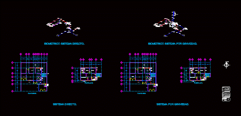
Autocad Hydraulic Blocks
Hydraulic Symbol Category: Hydraulic Valves. Free electrical, electronic, pneumatic and hydraulic symbols library with DXF, DWG and Visio formats, ordered by categories. AutoCAD and AutoCAD LT have a limited set of symbols which are available on the sample tool palettes. One can find an icon on the Ribbon panel - View tab - Palettes panel, to launch the palettes. Alternatively, one can use the keyboard combination CTRL+3 to access the same palettes.
Insert hydraulic components from the icon menu. The hydraulic symbol library in AutoCAD Electrical includes filters, valves, cylinders, pressure switches, motors, pumps, meters, restrictors, quick disconnects, flow arrows and more. The hydraulic symbol library consists of all the hydraulic symbols. Lifts, Elevators, useful CAD library of AutoCAD models, CAD blocks in plan, elevation view. Our Electrical & Fluid Power Block Library contains over 2850 AutoCAD symbols, all accessible with a drop down menu system. The block library runs in either AutoCAD or AutoCAD LT and includes circuit breakers along with pressure, limit, float and pull cord switches and a whole lot more. Lifts, Elevators, useful CAD library of AutoCAD models, CAD blocks in plan, elevation view.
Insert hydraulic components from the icon menu.

Autocad Hydraulic Symbols Free Download
The hydraulic symbol library in AutoCAD Electrical includes filters, valves, cylinders, pressure switches, motors, pumps, meters, restrictors, quick disconnects, flow arrows and more. The hydraulic symbol library consists of all the hydraulic symbols. It is found at UsersPublicDocumentsAutodeskAcade {version}Libshyd_iso125.
Insert hydraulic symbols
- Click Schematic tabInsert Components panelInsert Hydraulic Components. FindNote: By default, an expanded panel closes automatically when you click another panel. To keep a panel expanded, click the push pin icon in the bottom-left corner of the expanded panel.
- In the Insert Component: Hydraulic Symbol dialog box, select the check box for Vertical.
- In the Insert Component: Hydraulic Symbol dialog box, click the General Valves icon.
- In the Hydraulic: General Valves dialog box, click Shut Off Valve Open.
- Respond to the prompts as follows:
Specify insertion point:
Select to place the valve in the upper left corner of your drawing
- In the Insert/Edit Component dialog box, specify:
Component Tag: VAL2
Click OK.
- Repeat steps 1 - 3.
- In the Hydraulic: General Valves dialog box, click Checkvalve Flow Left.
- Respond to the prompts as follows:
Specify insertion point:
Select to place the check valve below the shut off valve
- In the Insert/Edit Component dialog box, click OK.
- Click Schematic tabInsert Components panelInsert Hydraulic Components. Find
- In the Insert Component: Hydraulic Symbol dialog box, click Motors & Pumps.
- In the Hydraulic: Motors and Pumps dialog box, click Fixed Displacement.
- In the Hydraulic: Fixed Displacement dialog box, click Uni-Directional Pump.
- Respond to the prompts as follows:
Specify insertion point: Select to place the pump below the check valve
- In the Insert/Edit Component dialog box, specify:
Description: Line 1: Hydraulic Oil Pump
Click OK.
- Insert another Shut Off Valve Open below the Hydraulic Oil Pump.
- Click Schematic tabInsert Components panelInsert Hydraulic Components. Find
- In the Insert Component: Hydraulic Symbol dialog box, click Filters.
- In the Hydraulic: Filters dialog box, click Filter.
- Respond to the prompts as follows:
Specify insertion point: Select to place the filter below the shut off valve
- In the Insert/Edit Component dialog box, specify:
Component Tag: FI2
Description: Line 1: Filter
Click OK.
- Click Schematic tabInsert Components panelInsert Hydraulic Components. Find
- In the Insert Component: Hydraulic Symbol dialog box, click Miscellaneous.
- In the Hydraulic: Miscellaneous dialog box, click Reservoir.
- Respond to the prompts as follows:
Specify insertion point: Select to place the reservoir below the filter
- In the Insert/Edit Component dialog box, click OK.
Issue:
Where to find symbol libraries for AutoCAD and AutoCAD LT.Solution:
Autocad Hydraulic Blocks Free
AutoCAD and AutoCAD LT have a limited set of symbols which are available on the sample tool palettes. One can find an icon on the Ribbon panel -> View tab -> Palettes panel, to launch the palettes. Alternatively, one can use the keyboard combination CTRL+3 to access the same palettes. That said, that is the sum of the symbology available within the application.
Some symbols can be found in the sample files that come with AutoCAD. These are located:
C:Program FilesAutodeskAutoCAD 20xxSampleen-us
There are however other resources available for block libraries, the following are just a handful found using a Google search:
